Configuring Patch Panel Connectivity
Connectivity internal to a patch panel can be configured using the Patch Panel Connectivity feature. This allows you to configure the internal connectivity of the front and rear of the patch panel before adding it to your inventory. When a patch panel is selected in the Infrastructure Explorer, the front and rear of the patch panel will automatically be displayed in the Connectivity Wizard.
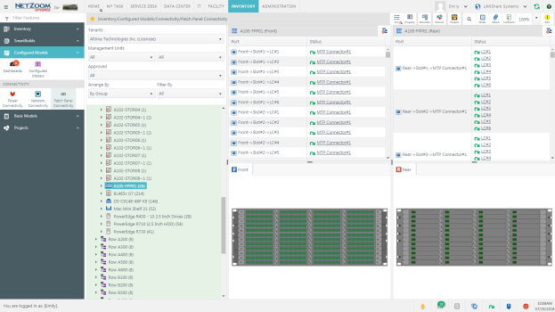
Feature Path: Inventory/Configured Models/Connectivity/Patch Panel Connectivity
Connecting Front and Rear ports.
- To map the internal patch panel connectivity of a patch panel, select the patch panel in the Infrastructure Explorer. The front and rear ports of the patch panel will be displayed.
- Select one port on the front and one port on the rear in the Connectivity Wizard.
- Click the
 icon. The selected ports will be connected.
 - Repeat steps 2 and 3 as needed to map the internal patch panel connectivity.
Breaking a Connection
- To break a connection, select one of the connected ports in the Connectivity Wizard.
- Click the
 icon. The selected port will be disconnected.
Note: When breaking one-to-many connections, click the disconnect icon on the single-port side to disconnect only that port, click the disconnect icon on the multi-port side to disconnect all connected ports.
Disconnecting All Ports
To disconnect all ports in a patch panel, click the  icon. All connections made will be broken.
Available Quick Actions
- List View
- Properties
- Slots and Ports
- NetZoom Device Library
- Tenants
- Reports
- Search
- Add Notes
- Attach a File
- Zoom
- Quick Help