
Using Add-in in Design and Diagramming Projects
NetZoom Visio Add-in provides the shapes and stencils needed to create both physical and logical network diagrams. This section summarizes common network design projects like creating a network diagram and a rack/chassis configuration.
First Project: Creating a Network Diagram
With NetZoom, you can create both logical and physical network designs and diagrams.
Logical network designs are most often used in planning stages, which requires general equipment icons that are used as placeholders before specific equipment is chosen.
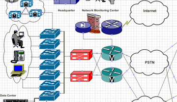
Once it is known what exact models will be used in the project, physical network designs can be created using the manufacture-specific equipment shapes that represent the actual equipment to be installed.
Searching Your Shapes
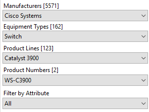
NetZoom allows you to search for shapes in multiple ways. You can search by Manufacturer criteria and select Manufacturer Name, Equipment Type, Product Line, and/or Part/Model Number by using entries from the respective combo boxes. Make the selections and press the
 icon.
icon.
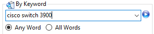
Or, search By Keyword using common equipment terms or other search terms that identify the equipment. Type in the entry and press the icon. By Keyword will filter the results of the Manufacturer search also
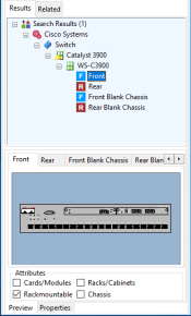
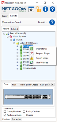
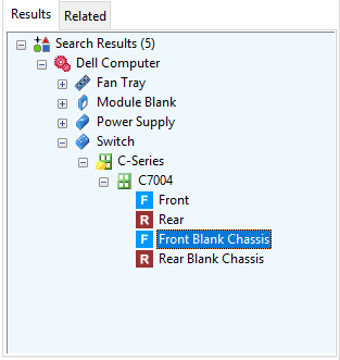
The search results are displayed in the Results pane. In the following example, the results are displayed in the tree view. The properties and a preview of the selected device are shown at the bottom of the Results pane.
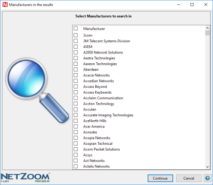
If your search results in too many matches
If too many results are found for the search, NetZoom will indicate that the results exceed the limit and present a list of manufacturers that meet the search criteria. Select one or more of the results provided and perform the search again by clicking the Continue button.
If your search did not return any results
Try your search using different criteria. If after that you still cannot find the shape you are looking for, then you should submit a free shape request online. See the section on “Right-Click Menu Commands” on how to submit shape requests. You may also submit shape requests by visiting https://service.netzoom.com
Dragging and Dropping the Selected Shape
From the Results or Related pane, you can drag-and-drop a shape view (Front, Rear, etc.) directly into Microsoft Visio by clicking on the shape and dragging it into Microsoft Visio’s window. The shape will be added to the Visio diagram as if it was drag-and-dropped from a Visio stencil.
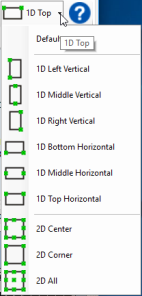
Selecting Connection Points
You can select the position of the connection points that are added to a shape using the ConnectionPoints drop-down box. The Default connection points are recommended to ensure devices Snap together properly and port-level connection points are created.
Basic Shape Elements
Before you build the rest of your diagram, you should learn some basics about the shapes themselves.
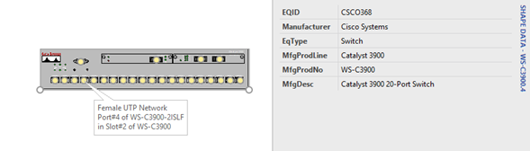
NetZoom shapes are embedded with various properties and specifications. They include model numbers and product dimensions, just to name a few. You can view these properties by right-clicking on the shape and using Microsoft Visio’s Data/Shape Data… command to view these properties.
NetZoom shapes have built-in connection points that match data ports, power ports, and equipment slots. These true-to-life shapes let users connect equipment and configure racks and chassis-based equipment, just as they would in the actual network.
Right-Click Menu Commands
In Search Results, the right-click menu offers many useful commands. These contextual menus let you create favorite sets of stencils, preview shape views and view properties. They also offer access to helpful services for NetZoom subscribers only.
The Open Stencil command creates and opens a Microsoft Visio stencil for the selected equipment or equipment shape view.
On a shape view, the Add to Microsoft Visio command adds the selected device view to the Microsoft Visio page.
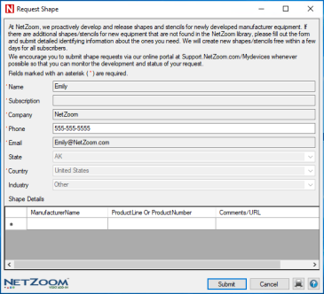
The Request Shape command displays the following form for requesting equipment shapes from NetZoom. Fill in as much identifying information as possible to reduce the time to create the new shape. The status of Shape requests can be tracked using the customer service portal found at https://service.netzoom.com
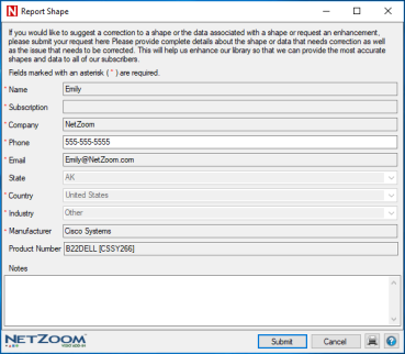
The Report Shape command displays the following form for reporting errors in equipment shapes. This form comes pre-filled with information about the current selection and your subscription. Add additional comments to describe the issue that is being reported.
The Visit Website command launches an internet browser to show the manufacturer website of the selected device.
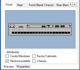
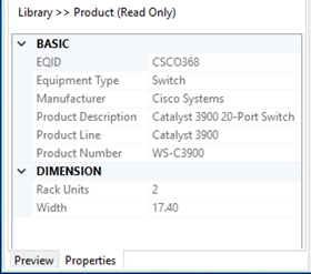
Preview and Properties
The Properties pane is separated into two tabs: the Preview and Properties tab. The Preview tab displays graphical views of the selected equipment shape view. The properties tab displays details for the selected equipment.
Scaling and Sizing Equipment Shapes
All NetZoom shapes are made with scalable vector graphics. This allows the user to scale shapes to any size without losing image quality and resolution.
To scale a shape, click and drag the mouse from any of the boundary connection points.
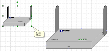
For a device that is rack-mountable, you can extend its width to fit a selected rack cabinet. For example, this is used when connection “ears” are needed to fit a device onto a rack of greater width.
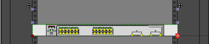
Connecting Equipment Shapes
To view the available connection points, click on a shape. The yellow diamonds on the equipment are the connection points that represent ports or other points of connectivity. When you hover the mouse over a connection point, tooltips display helpful port and slot information.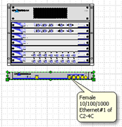
To connect two NetZoom shapes, use Microsoft Visio’s connector tool to draw a connector from a selected port on one shape to the selected port on another shape. Using this feature, you can show detailed cable and wiring information in your diagram.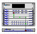
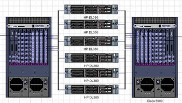
Project: Configuring a Chassis
With NetZoom’s built-in connection points, you can show the precise parent-child relationship between components, build racks and configure a chassis.
To begin, select an empty chassis of your choice. Select a 2D Front Blank Chassis view and drag the shape view into Microsoft Visio.
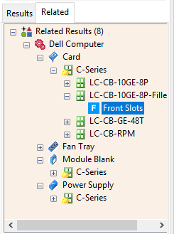
If the chassis has related shapes, the Related tab will display available modules that are compatible with your selected chassis.
Select the module shape view that you want to use and drag it into an empty chassis slot.
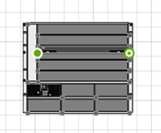
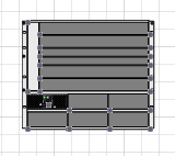
Using this method, the user can completely customize any chassis to the desired configuration. 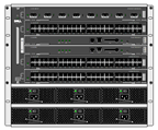 Fully configured chassis
Note: If the selected shape does not appear to have related shapes available, you can submit shape requests online. See the section on “Right-Click Menu Commands” for how to submit shape requests. You may also submit shape requests by visiting https://service.netzoom.com
Project: Configuring a Rack using the RackBuilder Template and Integrated NetZoom Visio Add-in
NetZoom Visio Stencils offers all the equipment shapes you need to design and diagram entire racks. Use the RackBuilder template in Microsoft Visio to make configuring a rack quick and easy.
The RackBuilder template lets the user configure both sides of the rack simultaneously. As a rack-mounted device is dragged into one view of the rack, the template automatically adds the corresponding other view of the device to the other side of the rack
Open the Visio application and create a new document with the RackBuilder template to launch the NetZoom Visio Add-in in integrated mode.
Note: The NetZoom Visio Add-in will automatically launch when opening a RackBuilder diagram or starting a new RackBuilder diagram.
To configure a rack:
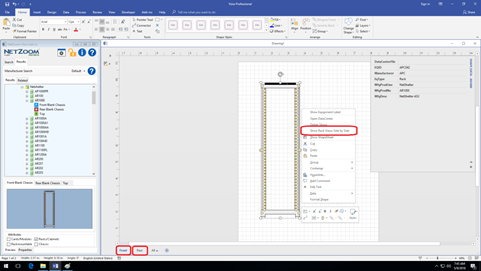
- Search the desired rack
- Drag the rack into Microsoft Visio. If you are using the RackBuilder template, you will see both the front and rear views of the rack in different tabs. If you right-click on the rack, you may also choose to view both sides at once by selecting the Show Rack Views Side by Side command.
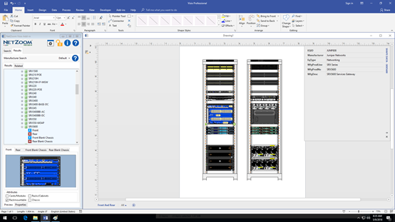
- Search for the first rack-mounted shape you want to use.
- Drag-and-drop the equipment on to the Microsoft Visio page. Then drag it to the desired rack unit making sure it connects to the rack. You may reposition the equipment to a different rack unit by dragging it to the appropriate location and reconnecting it.
- Notice that the other view of the rack is also built as you configure one side
Customizing NetZoom Visio Add-in Using Settings and Options
You can customize your entire NetZoom experience through Settings and Options using the  icon on the toolbar. Settings and Options are divided into four sections:
- General: Setting for drag sensitively, background colors, automatic log purges, and reminders for subscription expiration.
- Property: Settings for displaying property details and displaying dimensions in inches instead of centimeters.
- Library: Settings for the device library service and search options.
- Microsoft Visio: Settings for connection points, tooltips, labels, the RackBuilder wizard, and other Visio options.
General Settings
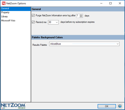
Purge Log
The Purge NetZoom Information error log field will automatically purge the error log after a set number of days if checked.
Subscription Reminder
The Subscription Reminder field will notify you a set number of days before your subscription expires, if checked.
Palette Background Colors
The Palette Background Colors field will change the background color that displays in search results.
Property Settings
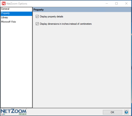
Display Property Details
This option will determine if shape data is added to the equipment shape when it is drag-and-dropped into Visio.
Display dimensions in Inches instead of Centimeters
This option will display the dimension values in inches instead of centimeters everywhere in the properties pane. By default, dimensions are given on a US measurement units scale.
Library Settings
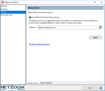
Library Source
The Library Source field allows the user to set the address of the device library source. For most users, this will be NetZoom’s Cloud Library.
Search Options
The Search Options tab displays search options.
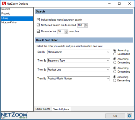
Include Related Manufacturers in Search
This option will determine if a search will include any related or acquired manufacturer’s equipment or only the selected manufacturer.
Notify me if Search Results Exceed X
Certain search criteria can produce many results, which may impact the performance of the product. This option allows the user to limit the number of search results that can be retrieved. If a search results in more results than the number specified, the user will be notified and he must refine the search criteria.
Remember last X searches
This option lets the user determine how many previous NetZoom searches to remember if at all. The previous searches appear in the keyword search drop-down.
Results Sort Order
Here the user may select the ordering or grouping of the search results in the Tree View. Results can be presorted by manufacturer name, equipment type, product line, and product number. Set the sort order by choosing the fields in descending significance and then the choose Ascending or Descending order.
Microsoft Visio Options
NetZoom works with Microsoft Visio (Professional 2013 or 2016) as companion (add-in) software. Microsoft Visio is a diagramming application whose drawing surface NetZoom utilizes to allow you to drag and drop shapes and create your network and data center diagramming projects natively.
NetZoom has many advanced features when used with Microsoft Visio. There are multiple that can be set within each tab that affect shapes dropped on Microsoft Visio. Each tab is explained below.
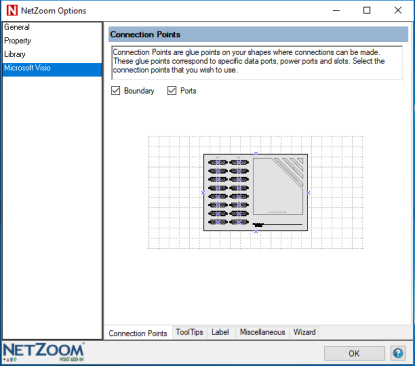
Connection Points
Connection points are glue points on NetZoom shapes where connections can be made. These glue points correspond to specific data ports, power ports, shape boundaries, and slots. This setting controls what types of connection points are applied to every NetZoom shape you drop into your project. In the Connection Points tab, check where you wish to view connection points. Connection points can be provided on Boundary positions and/or Ports.
Note: The Ports setting also controls the connection points setting in the results.
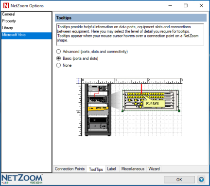
Tooltips
Tooltips appear when hovering the mouse cursor over a connection point on a NetZoom shape. Tooltips provide helpful information on ports, slots, and connections.
In the ToolTips tab, select the type of tooltips you wish to display. You may select Basic tooltips, Advanced tooltips, or you may choose to view None. Basic tooltips will display ports and slot names. Advanced tooltips will display slot names along with a detailed description of the ports within the equipment.
Labeling
NetZoom can apply labels to shapes used in your drawings to help identify the equipment. Labels can display any of the properties, and can be placed wherever you wish. You can apply customizable labels to each piece of equipment. By default, there are no labels. When dragging and dropping equipment shapes from the NetZoom library, it will only apply non-floor non-editable labels to all the shapes. You may create and display up to three labels.

- Within the Label tab, select Label Placement depending on which kind of equipment you wish to display labels on. Select Floor Equipment if you wish to apply labels on floor equipment. Unselect Floor Equipment if you wish to display labels on rack mountable equipment.
- Next you may select the Label Position of your choice from the drop-down menu.
- Next select a property from the drop-down menu that you wish to display as the Label Text.
- Check the Editable option if you want your labels to be editable. This means the labels can be modified manually once they are displayed. You may create only one editable label. Only the last editable label will be applied as editable to all shapes. Non editable labels will be applied appropriately to floor or non-floor items depending on the label definition.
- Once you are done, click the icon to add the label definition below. You may create up to three labels for NetZoom shapes.
- You may remove a label by clicking on the icon beside it. Labels can be modified here as well.
Miscellaneous
Using the Miscellaneous tab, you may select how you want to view stencils in Microsoft Visio when
The Open Stencil command is used to create stencils. Modify the Stencil Display options as desired. Stencil views can display Icons, Names, and/or Details.
Rack mountable devices can be scaled to fit into racks and cabinets. Select how you wish to scale rack mountable devices within racks. Select your preferred Rack Mountable Scaling as Fixed or Variable. Fixed means the equipment will remain fixed size while the brackets of the rack mountable equipment will be scaled so it fits in the rack unit. Variable means the equipment itself will be stretched to scale, so it fits horizontally in the rack unit.
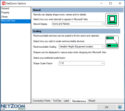
Shapes can be displayed in various sizes when dropped into Microsoft Visio. Select your preferred Shape Scale Factor as 1:10 or 1:1.
RackBuilder Wizard
The RackBuilder Wizard settings are used by the RackBuilder Template. These let you diagram rack elevations over an existing background template that is saved as a Microsoft Visio file.
Check the Background File option if you wish to provide a background file. Next click the … button to browse for a Microsoft Visio Background Template File. If you are using a Microsoft Visio file with multiple pages, use the drop-down menu to select the desired background Page.
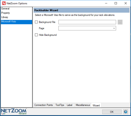
Checking the Hide Background option will hide the backgrounds from the templates.
Last Updated: Friday, September 07, 2018
NetZoom, Inc.